Introducing: GEX
I don’t update this site as often as I perhaps should, but if you follow me on Mastodon it would be hard to miss my yellings at various development tools and frameworks with ever increasing cadence.
Since early spring 2017 I’ve spent most of my free time working on ESPTerm, a WiFi terminal project I mentioned in the previous post here. It’s now complete as far as the original plans go, with many additional features added that I didn’t think of until later, and a few more still planned. Those additions to ESPTerm are based on suggestions from the slowly growing community, as well as my experience with actually trying to use it and finding what could be improved. The module is presently being tested by some students in an embedded electronics course, which will hopefully bring in more feedback and help push it further.
ESPTerm’s development is now moving much slower though, as I started working on my diploma project which needs to reach its “product” state, that is, become a fully usable device, by around April next year. That project is, of course, GEX.
What is GEX trying to solve
GEX is an abbreviation of “GPIO EXpander” or “General purpose EXpander”.
I’ll start by giving some background and highlight the problems I’m trying to solve with it. The rest of the article will focus on challenges, already encountered and still waiting to be tackled, and some interesting implementation details.
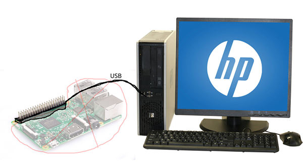
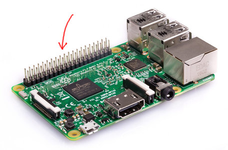
Looking at the Raspberry Pi, you’ll notice the main feature of the board is the GPIO header, a row of pins you can use for controlling various external components like LED strips, sensors, motors, physical buttons, displays etc. Besides the obvious selling points like low price, small form factor and relatively high processing power, this header is in my opinion the Raspberry’s main strength. Of course, many clones and competing products have popped up since the introduction of the Raspberry Pi, but they’re mostly just variations on the same theme, a tiny cheap computer with GPIO.
What, though, if you wanted to do things like controlling LEDs from your PC or laptop? How about reading a temperature sensor you stuck outside the window? We no longer have the ubiquitous parallel port that could be used for all kinds of hacks, now even it’s companion RS232 is a rarity in newer computers. Along with PS/2 and joystick ports, all those connectors were replaced by USB. Despite some efforts to fragment the standard by the likes of Apple, USB is now truly a Universal Serial Bus. Almost any gadget you can think up now uses USB.
The problem with USB is that it’s doing many things and so the protocol is very complicated and not very welcoming to beginners trying to use it in their projects. Thankfully the USB physical layer is now available in many microcontrollers, implemented right in the silicon. Manufacturers of those chips usually provide a library for working with USB in a more abstract, high level manner. All put together, this means USB is quite accessible for embedded projects, given the developer invests a couple hours in reading the specification or at least some guides (or… ahem… pays attention in the class). USB is far from straightforward, but it’s also not entirely deserving of the aura of mystique it’s often attributed. I’m not talking about USB 3.0 now, that’s dark magic.
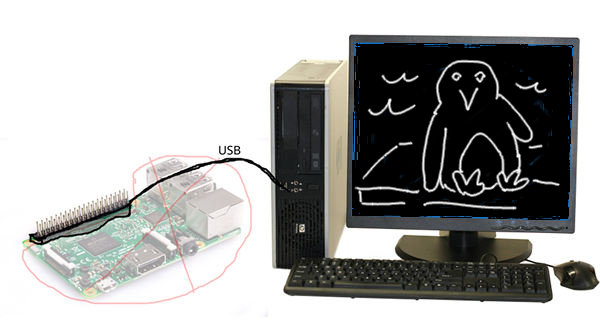
However, you’re still stuck with implementing an embedded firmware just to blink some lights from the PC. Couldn’t this be easier? Wouldn’t it be neat to have something like the Raspberry Pi’s GPIO header available on the PC? This idea isn’t entirely new, of course. A related project is Bus Pirate which serves mainly as a tool for debugging and testing various protocols, and there’s also the whole Firmata thing which–if I read the docs right–let’s you access Arduino’s pins remotely via the serial port (I think?).
I’m not really satisfied with anything I found so far, for one reason or another, so here we are, inventing a better wheel.
GEX’s objectives
Here’s a summary of the project’s key points. GEX should be:
- An easy way to access the “physical world” from any PC / laptop without having to write embedded code or get your hands dirty with USB.
- Affordable. It should work with some of those ridiculously cheap boards from eBay, for example, and making a custom board shouldn’t be too hard either.
- High level. You shouldn’t need to know anything about the used microcontroller to use e.g. SPI or toggle a pin.
- Cross-platform. I’m working on Linux and have no desire to use it anywhere else, but I want it to be accessible for everyone.
- Performant. I want GEX to be able to drive graphic displays and animate LED strips, as well as e.g. driving motors with feedback control. How this works out is yet to be seen, but it’d be neat.
Plans, in more detail
I want GEX to be really user-friendly, to Just Work. At the highest level, it’ll be a device you plug into USB, configure it to do what you want (e.g. designate some pins as output or input, set up the SPI port), and then access it using some C, Python or perhaps MATLAB API. There might be some daemon process running on the PC to facilitate multiple access.
GEX should be cross-platform and the configuration must be easy and user-friendly. I got inspired by ARM mbed here: mbed boards appear as USB Mass Storage when you plug them in (usually together with virtual comport and some debugging interface). The Mass Storage class in mbed is used for flashing firmware by drag&drop, you just copy the file onto the virtual disk, and it’ll get written to the target chip’s flash memory.
Here’s an example of the virtual disk provided by mbed:
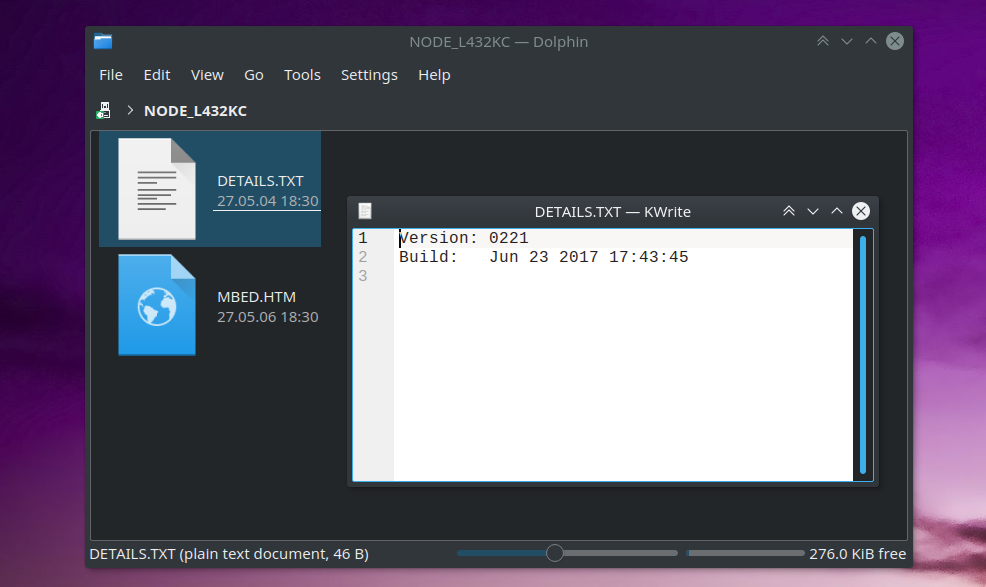
How this all works is really messy and hard to grasp; basically I have to generate pieces of FAT16 filesystem (the MBR, FAT and all that) on the fly and serve them to the PC, as well as parse its write attempts. Fortunately I could reuse parts of the actual mbed code for this.
In GEX, this virtual disk will be used to expose configuration files in the INI format. You simply open the file, edit some fields, save, and the changes will be applied. It would be annoying to have it pop up every time you boot your PC or connect the board, so I want to have a “LOCK” jumper which will hide the configuration drive when closed.
Now, regarding the actual communication, there are multiple choices: HID USB class, CDC/ACM class or a custom class. For now I’m focusing on CDC/ACM, which is nothing but a virtual comport. That should make it work nicely with Windows without having to research writing drivers and going through that certification nonsense. One slight variation on this should be the option to hide the comport and access it via libusb as “vendor specific class”, maintaining the same USB endpoints but just changing the class in the descriptor. Whether this will work well or not is yet to be seen. So far I know this trick works for hiding the configuration disk with the LOCK jumper.
Perhaps the most important part of the device is the “meat” of the whole application, functional blocks. There should be one block for each peripheral or function, like Pin, SPI, ADC sampling, frequency measurement etc. Those blocks can be instantiated using the config INI file and then will be addresable via the communication interface. The settings are persisted in a binary format at the end of the built-in Flash memory.
Choosing the tools
Now, how? I picked STM32, ARM Cortex-M microcontrollers which I used in many previous projects and development boards with them are really cheap, e.g. on eBay (search for the “Bluepill” board). Those chips have a lot of nice peripherals, are fast and have quite a lot of RAM and Flash–at least compared to the pittance you get in Arduino.
For the initial development I chose STM32F103C8T6, that’s the chip on the Bluepill board. It has 64 kB Flash and 20 kB RAM, which is not much but should be sufficient for a start. This imposes some constraints on the development and makes me work more carefully with the resources available. That’s important for porting it to even smaller devices later. Switching to a larger STM32 should be straightforward; I have plans to support at least STM32F303 and STM32F407. Adding support for STM32F042 would also be very nice, but it’s too small for the full system as I have it planned, so it’ll likely come without the virtual disk part and settings will be loaded using the virtual comport, which is a feature I want to have in the regular build as well, actually.
To set up the firmware project, I decided to use STM32 CubeMX. This tool can generate the basic project structure for many IDEs, unfortunately the good ones are all for Windows and paid or limited and STM32SW4, which works on Linux, is really bad (it’s based on Eclipse, which pretty much says it all). But: The tool can now also generate a Makefile! Aha! So I made it work with CLion by supplying a dummy CMakeLists.txt and can now enjoy all the CLion goodies with a student licence. It should be possible to use CMake directly but I had some poor luck with that. There’s a small gotcha, the Makefile is broken after you generate it by CubeMX, but the fix is simple–deduplicate source files and fix the compiler path.
As for the software stack, GEX is based on FreeRTOS. I never used RTOS before, so learnign that is a nice by-product. This is also the first time I really work with USB, luckily the STM USB Device library works quite well.
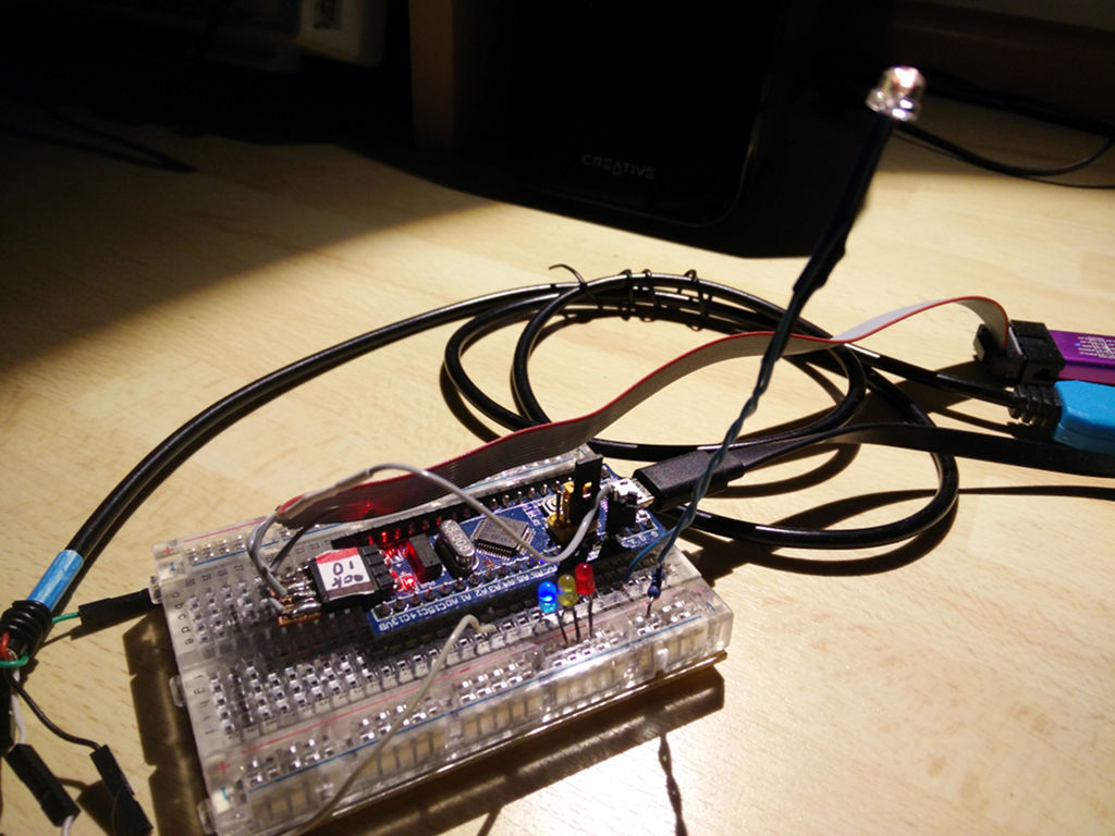
Here’s my test setup with the STM32F103 Bluepill:
Progress & what’s next
I really want this to succeed, mostly for selfish reasons of building a neopixel ambient monitor backlight with it after it’s advanced enough, so it’s moving fast. It should also give me the MSc diploma so that’s a nice bonus ;)
Here’s a diagram of the general structure to-date:
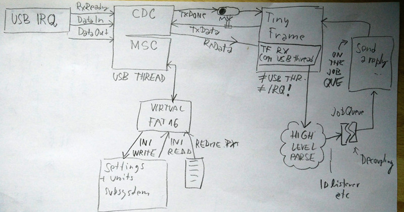
It enumerates, pops up in /dev/ and opens a “new disk” notification (even on Windows!). This means both the SCSI component and the virtual filesystem work correctly.
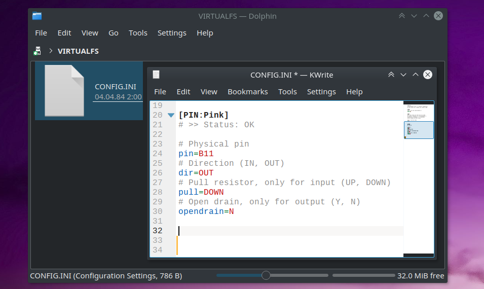
You can use the INI file to create instances of the Pin unit to light up LEDs on different pins. Blinking them is at not possible yet as I’m still working on the communication protocol. Virtual comport already works, though.
The LOCK jumper is also implemented, closing it makes the virtual disk invisible to the OS, unfortunately you need to re-plug the board for that to take effect, which is something I hope to fix.
What’s left:
- Documentation (this will be in the thesis, but I also want something standalone)
- The comunication protocol
- C/Python support library
- Some actual function blocks (now we have only Pin)
- To design a board??
If you’re interested in the project, follow me on Mastodon (@MightyPork@dev.glitch.social) and I’m sure you’ll get your fill of updates.
There will certainly be a new article here once it’s finished, and the code will go on GitHub–it’s already there, but private because I don’t want anyone forking my unfinished thesis project haha