Design for 3D printing in FreeCAD, part 1
Welcome to my short tutorial on how to use FreeCAD to draw models for 3D printing. I will try to summarize the basics and the techniques I use, so hopefully you can spend less time cursing FreeCAD and more actually drawing and printing.
FreeCAD is a pain to get into as a beginner, the learning curve is steep and the software is buggy and acts weird when not used just right. I have a theory why this is so - all the developers spent so much time using FreeCAD, thet no longer hit the bugs, so nobody spends time fixing them. Some things get fixed over time, of course - your mileage will vary.
Know your enemy
FreeCAD absolutely will do the following:
- Crash to desktop, losing your work
- Trash your project, so it’s faster to just redo everything
- Indefinitely freeze when you do something stupid (like, using the array function to make an array that’s a little too big)
- Things that worked before suddenly stop working and you can’t find why. Sometimes a restart helps… sometimes not.
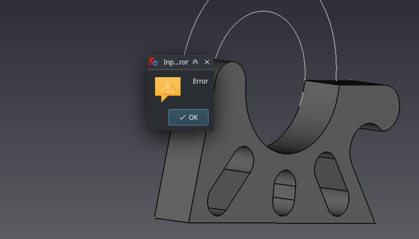
- Show cryptic error messages, like “Error” with one button: “OK”
Therefore, the first thing to get into your muscle memory is to save often, after every meaingful change, like you would with git commits. Also, create backup copies. There even is a special button to save a backup copy right in the main menu! The developers know.
You can put your peoject in git, but since the save format is binary, you can’t have nice things like branches and merging. It’s still better than nothing, I guess. Personally, I’m too lazy for that, I just fill my Models folder with trash and from time to time clean it up.
Now to some basic concepts.
FreeCAD basics
FreeCAD is the kind of software that tries to do everything, because, you know. CAD. This ranges from architecture, ABB-style robotic arm path planning (yes, really), techncial drawing, all the way to crazy things like finite element modeling. One notable exclusion is PCB design, they benevolently leave that to KiCAD.
I don’t mean to rain on anyone’s parade, but you can probably imagine that most of the things are experimental, unfinished, unpolished, or just generally half-assed, because they have like three users who really understand them, one of them the developer. There are unfinished and broken bits in 3D modelling as well, but for the most part, things work, if you know the tricks.
The way to switch between the different faces of what FreeCAD can do is called workbenches.
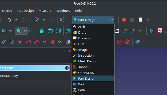
There are several workbenches that have some use in drawing 3D models, but I mostly use the Part Design workbench.
- Draft - might be useful to draw projections of your model, I still didn’t figure out how to use it
- Sketcher - you will spend a lot of time here, drawing 2D cross-sections to extrude; However, the switching happens automatically as you edit a sketch, you don’t generally open the Sketcher workbench through the dropdown menu.
- Spreadsheet - it’s basically a poor man’s Excel, with just enough functionality to be useful. You can define constants and formulas here, label your cells, then use the labels whenever you need a dimension.
- Part Design - this is my main workbench, it has all the toolbars you need for drawign a parametric 3D model.
- Part - feels like a more limited version of the above, I believe this is an older version. Some tools are duplicated from Part Design, but missing features.
- Meshing - intended for creating and modifying meshes, kind of like you would do in Blender. Of course, you will rather use Blender. This workbench, however, lets you export higher quality versions of your models for printing, so you won’t have the notorious low-poly pattern on curved surfaces.
TL;DR, start in Part Design. Spreadsheets make sense mostly for more complex models or models made up of multiple bodies.
Bodies… well. FreeCAD parts are made of bodies - these are contiguous 3D shapes, such that could be e.g. cast from resin without falling apart. This is a limitation that sometimes gets in the way. You can, nonetheless, have multiple bodies in a project. Bodies also figure in the “boolean operation” tool, but it’s rather confusing, so better leave that for later.
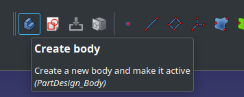
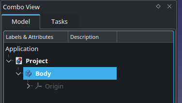
Let’s get started. Create a body, and activate it by a double-click in the project tree panel.
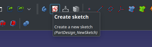
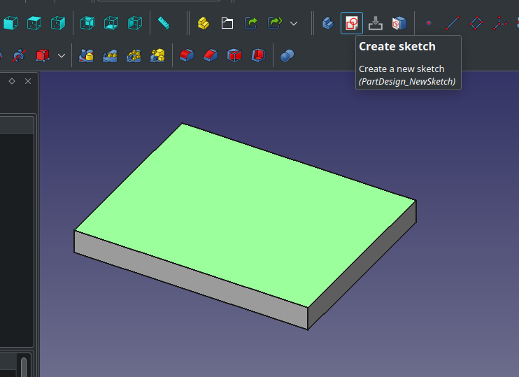
To create a sketch inside the body:
You will be asked to select the backing surface for your new sketch. In this case, you have a choice from the three planes, so just pick one, e.g. X/Y.
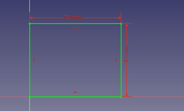
I will try to explain how to use the Sketcher in the next article of this series. For now, I made a rectangle:
All you need is … extrusion
Extrusions are a thing FreeCAD is really good at, and, conveniently, many 3D models can be drawn as a combination of additive and subtractive extrusions, lofts, revolutions and other fun and weird operations you find in the Part Design toolbar. The base of an extrusion is a closed shape, drawn in the Sketcher workbench.
A closed shape could be e.g. a circle or a polygon, but you can of course go more complex. This is sometimes called a Wire—if you see an error message about “unclosed wire”, that means you have a hole somewhere in the sketch. The hole may be hidden, e.g. two points are on top of one another but not actually the same. FreeCAD is very picky in this.
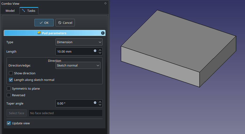
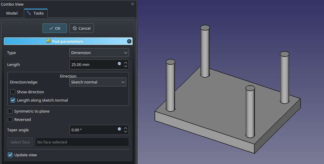
The most basic extrusion is called “Pad”.
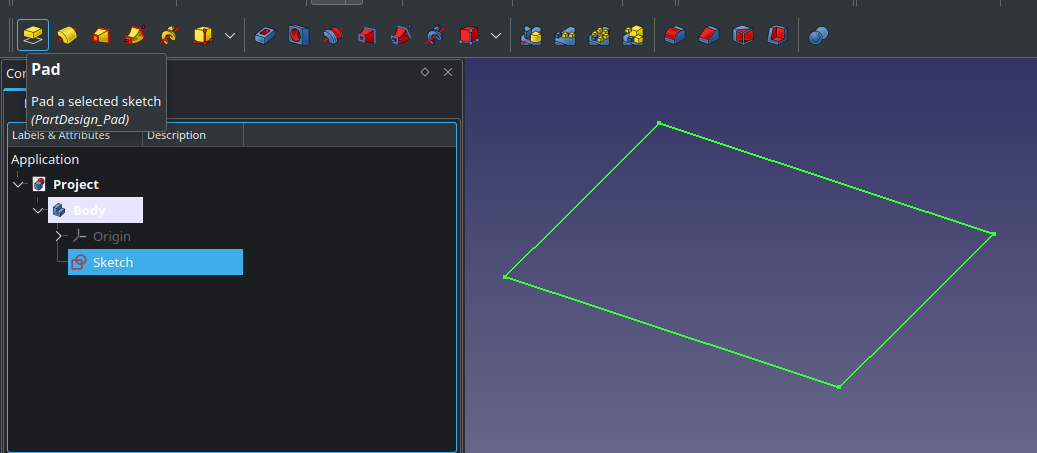
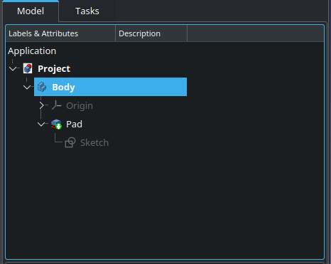
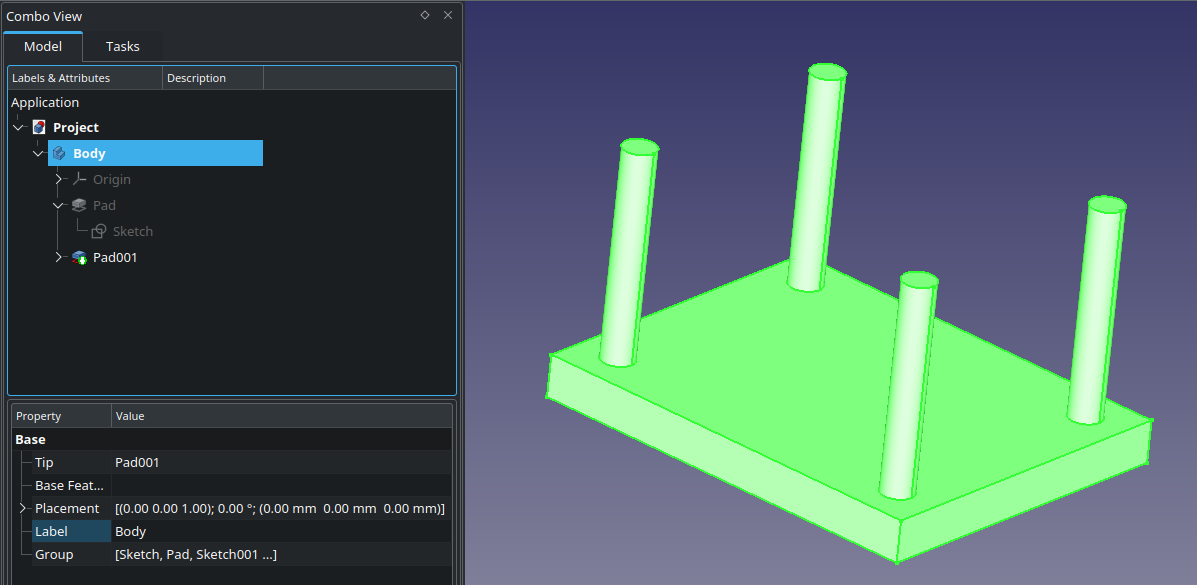
You now have the Pad object in your project viewer:
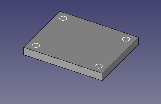
You can have multiple separate shapes in your sketch, so long as they become part of the body after you extrude it - imagine creating table legs by extruding 4 circles.
First, you select the base face - the sketch will attach to it. Then click the Create sketch button like before.
I created a sketch with four squares. Now if you pad it, you have a table. Note how this works - the body is still in one piece, so you can extrude such sketch without problems.
A note about proprity and dependencies
Do not be tempted to drag things around in the project tree! That is a surefire way to corrupt your project. It’s not clearly shown (or, more like, not at all), but some things have dependencies to things above them (or here, inside them). The order matters! This wasn’t explained anywhere, so I had to learn it by breaking my files a couple times. There are cases where dragging can work, such as for stand-alone sketches, but absolutely do not try to change order by dragging, or to move things between bodies. If you need to do that, use the context menu, there are options to move and re-arrange items. It’s stupid, but that’s what we have.
Keep in mind that in my demo, the legs sketch now depends on the first pad, and the legs pad depends on the legs sketch. If you go messing with any of the parent shapes, there’s a risk of this breaking your project. A good rule of thumb - start with the biggest shape, then keep adding and shaping it. Things like rounded edges and screw holes should be done at the end, so nothing depends on them and you can easily and safely change them.
A note about visibility
To toggle visibility, select a thing in the project tree and hit spacebar. You can e.g. hide an entire body. The way this works is sometimes a bit counter-intuitive, but visibility is generally hierarchical.
Printing your model
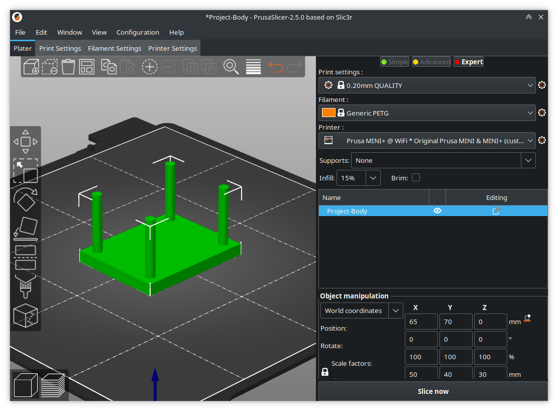
When you’re done with your model, you can quickly export it to a 3mf file (or stl, in older FreeCAD). Make sure the body you want to export is selected:
The produced 3mf file is ready for slicing:
Nicer export with Meshing workbench
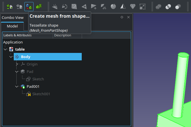
If you want smooth curves, switch to the Meshing workbench, then use “Create mesh from shape”.
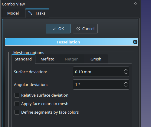
Adjust the export parameters as needed and hit export. I have a good experience with 1° angular deviation, but the produced file will be gigantic, easily many megabytes. Choose your compromise.
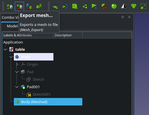
The meshed object is added to your project. Choose it and use the “Export mesh” button.
You can download the demo project here: table.FCStd
to be continued …