ESP8266 killing itself?
ESP8266, a popular WiFi chip with many undocumented “features”. Here’s one nasty one, which can cost you the WiFi module.
I’ve observed this issue on ESP-01 and ESP-12 modules, and heard it also occurs on ESP-03. I believe it’s safe to assume it can happen to any module.
Introduction
The ESP is a power hungry chip, normally using about 70mA with frequent short
current spikes (1us at about 400~mA). Those can, to a certain extent, be
suppressed by small ceramic capacitors. You’ll still be getting some Vdd ripple,
but that could be fixed with a choke (optional) followed by a larger capacitor.
Basic stuff.

However, the gotcha is at startup, where the ESP generates a burst of current
spikes (40ms of 200 to 400mA). You won’t fix that with a blocking capacitor.
Here’s a picture of the supply voltage on ESP-01, so you can get some idea about the current demands. The large voltage drops are due to the resistance of power supply cables, breadboard contacts etc. Here it effectively serves as a poor man’s current probe.
The Glitch
What is the glitch, you ask? It appears that if the voltage drops below a certain threshold on startup, especially if the voltage ramps up slowly (eg. if you used too large capacitors that don’t have time to charge fully) the ESP may enter a fault state with excessive current draw and a thermal runaway. Note that the issue also tends to occur in battery powered solutions, possibly due to the wifi core crashing, watchdog biting and triggering a reset.
The chip then sinks good 250~mA and cooks itself if you leave it that way for too long (more than a few seconds). This is especially “great” in case of the canned modules with an obviously worse heat dissipation.
A nice case illustrating the issue happened at the IBM’s BSRE2016 (an event for students all across Europe hosted in Winchester that I attended). There was an “IoT” activity with ESP-12 based modules powered by a 9~V battery that acted as MQTT nodes. We left them on overnight to collect data and the next day, maybe half of them were dead.
You’ll often experience this glitch when working on a breadboard. Chinese breadboards (read: the piece-of-crap eBay ones) can have HUGE contact and trace resistance (several ohms), and Ohm’s law dictates a proportional voltage drop, especially pronounced at the high currents the ESP demands during startup.
Solutions
Now how do we deal with this nasty problem?
I have no definitive answers, but some things you can try.
Blocking capacitors
As discussed above, you’ll want to add some good blocking caps to your module, and a choke if you want to protect the rest of your circuit from disturbance. However, this is not a very reliable solution, it works great for breadboard experiments, but won’t help if the voltage drops ie. because of battery discharge.
We need something more sophisticated (but keep the caps!)
External voltage monitor
Normally there’d be a built-in low voltage detector (or “voltage watchdog”), but it’s either faulty, or they didn’t bother adding it at all. Curiously, even the “Arduino” ATMEGA has one.
But we can check the voltage externally and shut the chip down if needed. The ESP has a reset pin, which you could use for this, as well as a shutdown pin CH_PD. They appear to work equally well.
You could buy a ready-made solution, such as the MCP120T-270; I’m planning to give those
a go myself and update the article with my findings. Or you could try to roll your own,
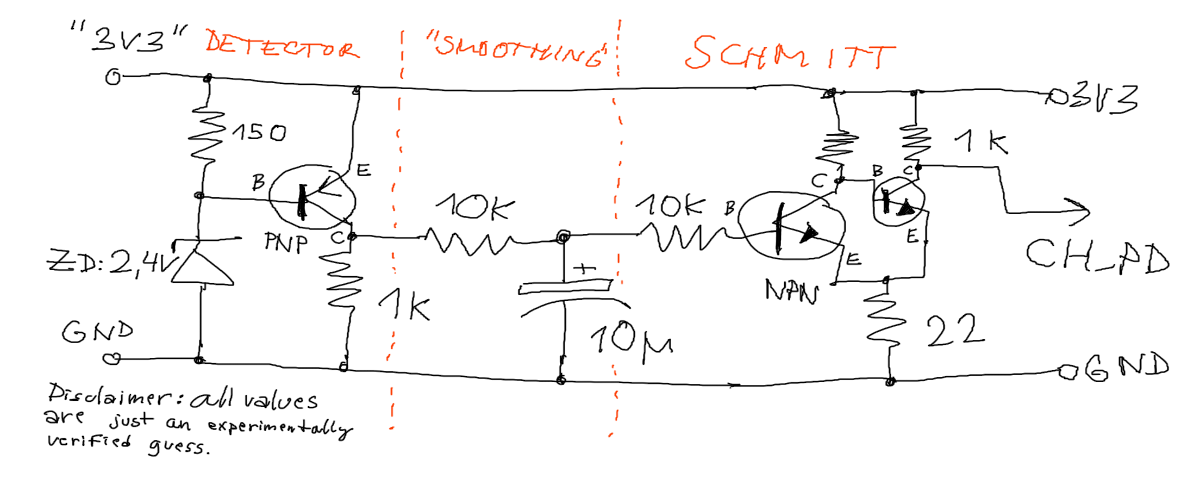
which can be done with a zener diode and some transistors:

The “smoothing capacitor” in the middle could be made smaller if you used larger resistors, this is just built from what I had laying around. It works alright.
The output is HIGH if the voltage stays above about 2.9~V. When it drops either due to the current draw or by battery discharge, the output switches LOW, disabling your ESP to save it from self-inflicted harm. One issue with this is that, if the drop is only due to the current draw on startup, it’ll enter a restart loop. This is probably fine, as the ESP never gets past the critical startup spike. It may hasten the demise of your battery, but it was near flat already anyway.
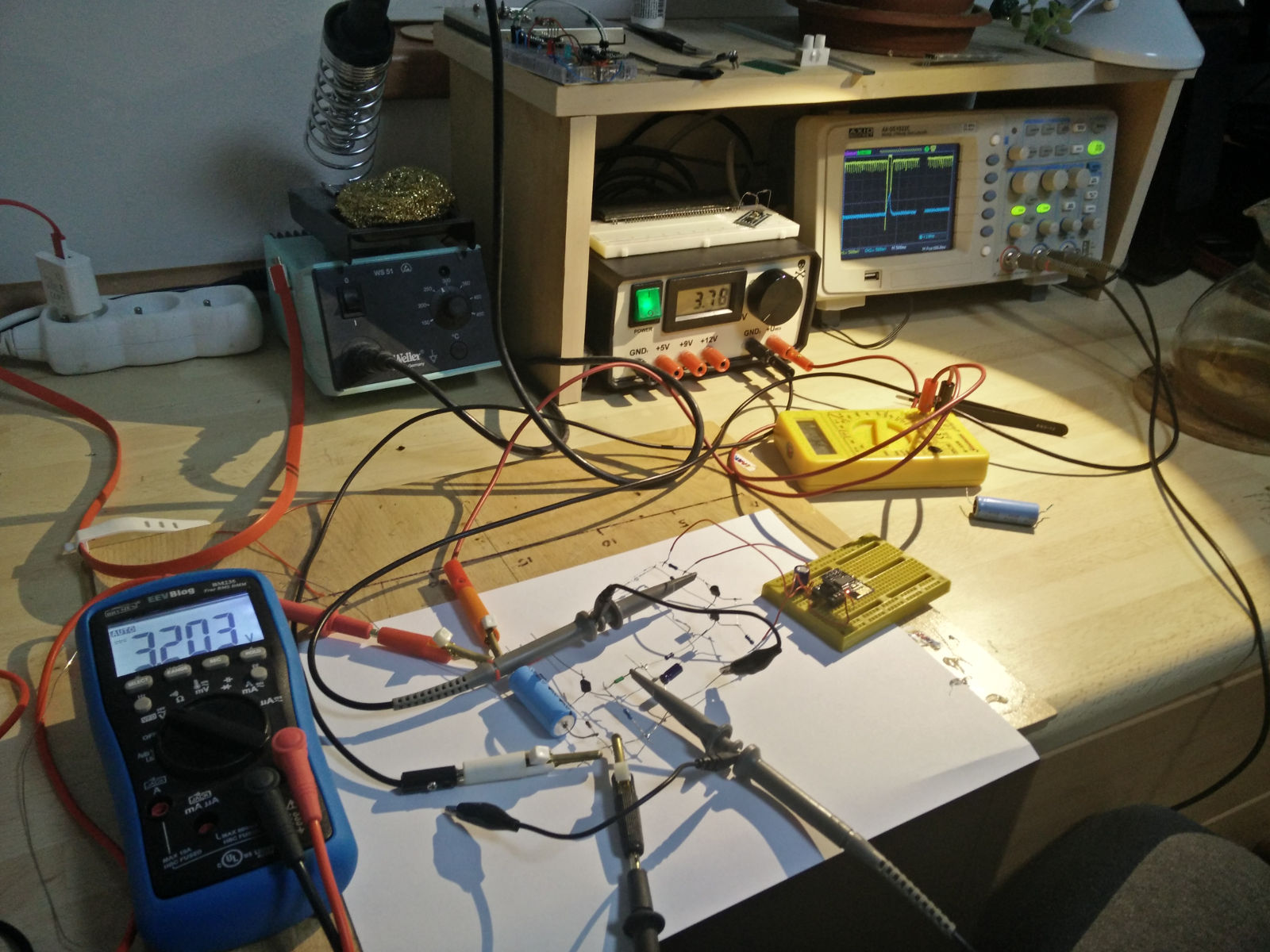
Here’s how I tried building it (gave up on breadboard):

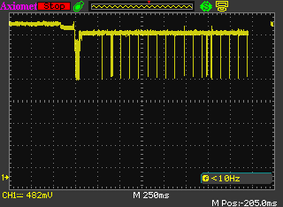
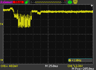
The following screenshots illustrate the operation of this circuit, first the “normal” run, then the restart loop I mentioned above.
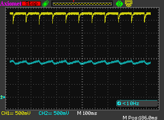
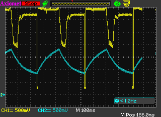
(Cyan - midpoint voltage, Yellow - CH_PD voltage - derived from Vdd)
Digital watchdog
An alternative to a voltage watchdog is a watchdog that asserts reset (or CH_PD) if it detects the application code isn’t running. There are manu such circuits available, so you could try to use that instead of monitoring voltage, which suffers from the previously mentioned reset cycling.
A gotcha here might be that if the watchdog is set to, say, 1 second, you still leave it for quite a bit in the fault state heating up. The 100-odd milliseconds after reset when the device stays idle won’t be enough to cool back down, so it might still kill itself.
You also can’t make the watchdog time too short, because it would bite before the processor had time to boot up and launch your application code (up to about half a second). You can try playing with the reset-hold time, if your watchdog supports that. It’s all just ideas here.
If you have a better solution, please let me know, I’ll try it out add also it here. If we could get rid of the cycling, or just reduce the number of transistors, that’d be quite awesome.