Wireless Terminal with ESP8266
Here’s a short write-up on a thing I’ve been working on recently. It lets
you add a wireless interface to any of your breadboard projects, conveniently
implemented as a terminal emulator accessible over WiFi.
Updated Jan 2018: see the bottom!
First, how this came about: It’s a small university project, a device for students to add some “IoT oomph” to their seminar breadboard builds. It’s aimed to be easy to use, hard to damage, and above all, fun to mess with for to the aspiring embedded hackers.
I used ESP8266 in my Bachelor’s project, so as the local “ESP expert,” the task of implementing this fell on me. I wanted to build something like this for some time anyway and also needed to check out some of the cheap PCB fabs out there, so I welcomed the idea. As it turned out, fabbing boards at OSH Park is fun!
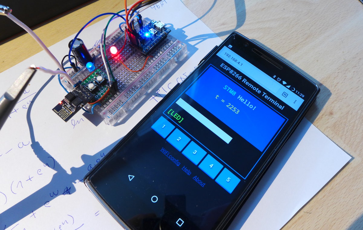
To give you a taste of the “cool,” check this demo with a STM8 board showing some simple UI on the screen:
Writing the Terminal firmware
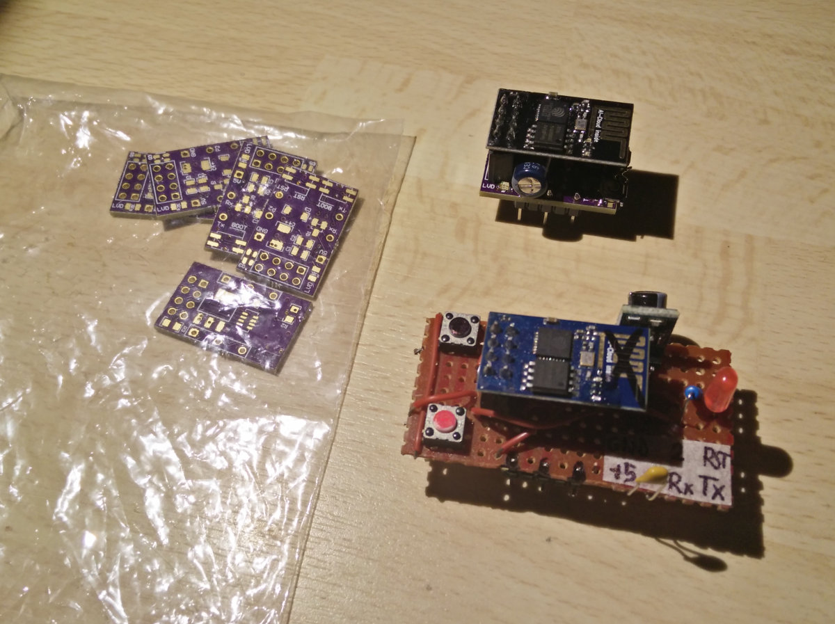
I used the “LoLin” ESP-12 breakout with on-board USB-UART for the firmware development, my go-to option when it comes to ESP prototyping. At the time of writing, those can be purchased for $7 on eBay, with free shipping. (We could have just bought some of those for the ESP terminals, but they are HUGE, not something you want on a breadboard already full of stuff.)
I based the project on my fork of SpriteTM’s libesphttpd (and the corresponding esphttpd project template).
Sprite did an amazing job there implementing a web server, complete with WebSockets and a simple template engine. My fork adds some small improvements and tweaks, such as a CORS header support, improved WiFi config page, and some bug-fixes. I chose to fork it instead of sending pull requests, since Sprite seems to largely ignore those. (But, Sprite, if you’re reading this, feel free to backport the changes!)
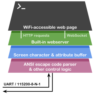
The web server takes care of the user-facing interface, and as for the terminal magic, there’s an escape sequence parser I implemented using Ragel. The entire screen is held in a large data array of characters and colors.
You can find the source code and binaries on GitHub, at MightyPork/esp-vt100-firmware. Check the readme there for setup instructions.
How to use it?
I wrote a rather detailed PDF to go with the project, so instead of repeating myself here, I’ll refer you to that document. Additionally, here’s a second PDF with some hints for implementing the master controller’s logic.
In summary, it implements most of the standard ANSI escape sequences, as described on the Wikipedia page, and some more (including a few custom ones). I also added mouse input support and five dedicated buttons that send ASCII codes 1 thru 5. Those can be used very easily, without having to do Complicated Things like parsing the mouse coordinates (sent as a custom escape sequence, btw).
First contact
After you connect to the WiFi, you should either be redirected to a Captive Portal landing page or you have to navigate to 192.168.4.1 manually. It helps to make a bookmark :)
On the hardware side, you get an 115200 baud UART at Rx Tx, debug output at GPIO2 and the low-active “force enable AP” button on GPIO0 (BOOT).
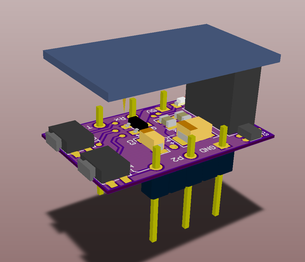
Building the breadboard adapter
Here comes the interesting part–from the drawing board (ok, well, Altium) to a soldered & working PCB made at OSH Park. It’s really simple, but doing it at home would be tricky, because of all the vias.
To skip forward, here’s the board in the OSH Park shared projects section. You can have a look at it there and even order it, if you’re so inclined. But first read to the end, there are some pitfalls!
Idiot-proofing the ESP-01
As I said earlier, one of the reasons for making a custom adapter is the footprint size. You don’t want a huge PCB on your already cluttered breadboard. In pursuit of this goal, the board I laid out is barely larger than the ESP-01 itself!
But there are other factors, too, as the board will be used by less experienced students. Mind, not all, and they should already know the basics when they get their hands on the ESP, but accidents happen.
Schematic & building blocks
Here’s the full schematic I went with (click to enlarge). I’ll explain what’s going on below.
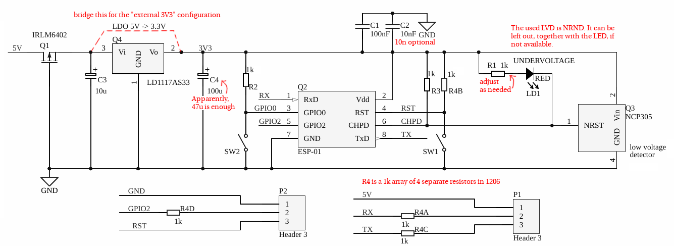
The ESP8266 doesn’t like its power supply reversed, and in the case of ESP-01, it’s far too easy to do. Worse yet, someone could connect it across the Rx and Tx pins, which are in the other two corners of the connector. To prevent this, I put 1 k protection resistors on the UART lines, and a PMOS in “diode configuration” at the positive supply terminal.
The ESP8266 under-voltage self-destruction fault state doesn’t help much, either. I decided to put a 3.3 V LDO (LD1117AS3.3) directly on the board, as prior experience taught me that the voltage drop on the resistance of breadboard wiring (up to several ohms!) is the primary cause of this fault. It’s an even bigger issue if you get your breadboard from eBay, some out there are really quite horrible.
As an additional countermeasure, I also fitted a low voltage detector (NCP305LSQ27T1G), which holds the CH_PD (enable) pin low when the power supply voltage falls below 2.7 V. With the LDO, this happens when the external voltage falls below around 3.5 V, leaving plenty of space for the voltage drop on poor breadboard connections if powered by 5 V.
Cost-saving options
If the LDO is bridged to save a few cents (an “external 3V3” configuration), the LVD should help avoid self-destruction on its own. Conversely, if the LVD is left out, a proper decoupling capacitor and the LDO should keep things safe on their own, for the most part.
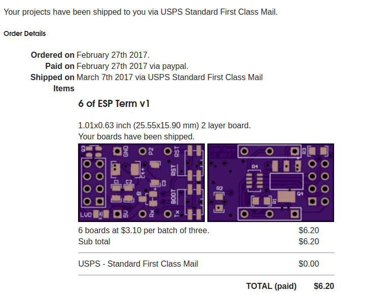
Getting the board made
This PCB was my very first order at OSH Park. From placing the order to it popping up in my mailbox, it took 17 days (or, 13 business days). Not the swiftest of services, but I’d say good enough. You can apparently pay up to get it faster, but there was no rush here.
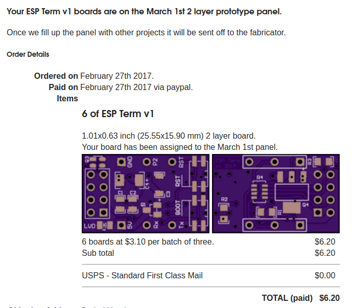
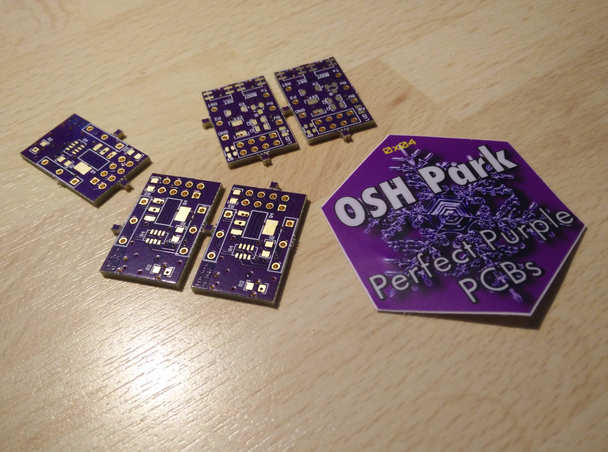
Funny thing, the test run of 6 pieces cost me just $6, while a similar order at a local fab house in the Czech Republic would’ve cost me something around $20, with postage fee on top of that. This was with free shipping from the friggin United States. How’s that possible, I have no idea–but it’s awesome!
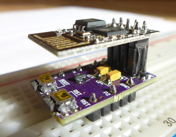
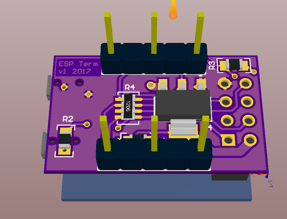
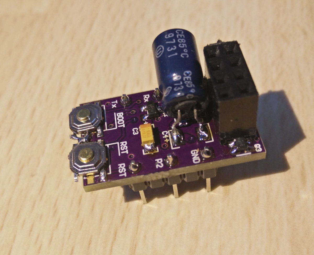
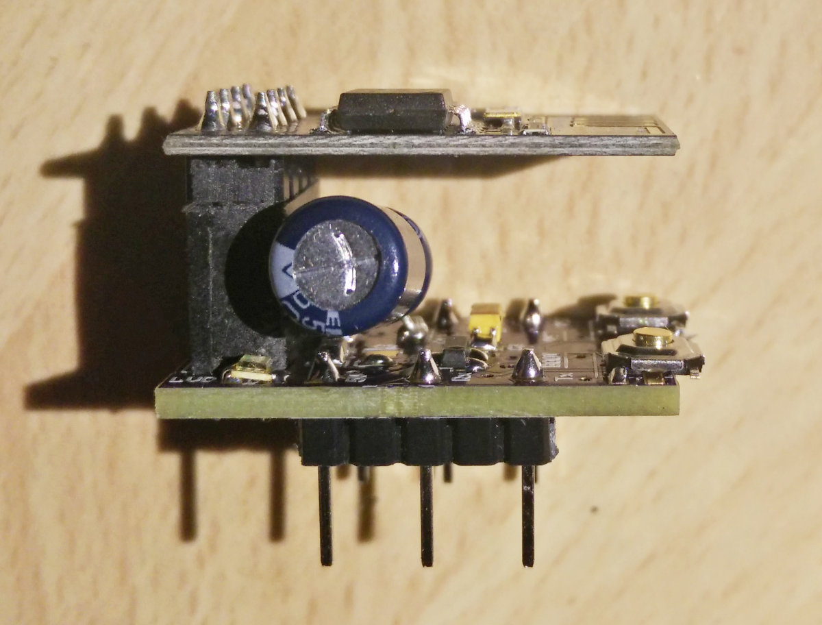
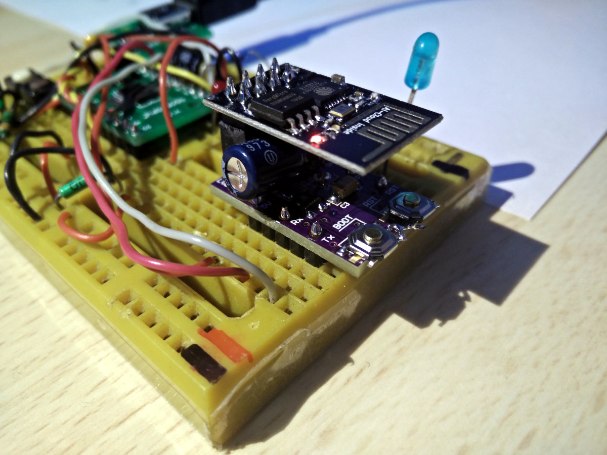
Putting it together
The part where you populate a board, connect the power and pray not to see any magic smoke. Surprisingly, it worked on the first try! Fair to say, there’s not much to get wrong here, and it’s also my 5th board in total if I count the excuse-for-a-PCB I made in the beginners’ OrCAD layout class.
Small Fails
No board is entirely without issues; luckily they’re quite minimal here.
The side-push “turtle type” buttons I ordered a month ago on AliExpress still didn’t arrive, so I had to make do with other ones. I could have foreseen this and made the footprints compatible with both. Oh well…
Another issue is with the large tantalum capacitor, for which I chose a footprint size B. Those are quite hard to get, most of the value range I’d like are C. But I found some, so this is mostly a non-issue.
And one more thing, which is again OK with me: it seems the LVD I used is out of production. I have a tape with 50 of them, but you won’t have much luck buying them on the likes of Mouser or Farnell. It may be tricky trying to find a pin-compatible replacement. Luckily, you can just leave it out if you trust the LDO and are a bit careful.
The board doesn’t sit in a breadboord too firmly, it wobbles slightly when you push at the ends. I believe that could be fixed by adding more pins, though I don’t really have use or space for more than those 6 I put there. This won’t be a big deal when I get the correct buttons, since pushing from a side is alright.
I’ll post some better photos when I get the buttons and caps sorted out. Check this space or my Twitter for updates!
So in conclusion, I’d say this turned out quite well. Board is working, everyone is happy, and OSH Park is awesome[1]. Planning to get my second purple sticker soon!
[1]: No #spon, they’re really great!
Update (end of 2017)
The project has grown quite a bit, mostly on the software side of things; we have an almost full VT100 compatibility and many extras from later models based on Xterm as a reference implementation. The modules have networking capabilities and awesome features like themeing or full UTF-8 support. Big thanks to friends who contributed their code or ideas. I’ve also set up a mailing list for any questions and to let people share interesting projects made with it.
The ESPTerm’s web user interface is being demoed on-line: espterm.github.io (obviously not running on an actual ESP8266). It includes a built-in help that will give you an idea about the things it can do.
I have built over 20 pieces of the module board and they are now being tested by students in the course this was designed for. The hardware was slightly updated for the second production batch but it’s very similar. You can find the source code repositories as well as better schematics and gerbers on GitHub: github.com/espterm
Here’s what the module looks like when fully assembled with the right parts: